Recalibrating Disk ][ Drives
Introduction
 This guide will focus on my personal experience regarding the recalibration of Apple Disk ][ Drives. Many old drives are still available today but often show problems reading and writing disks even after intense cleaning processes of the mechanics and the read/write-head. One possible reason for drive failure can be the driving system – especially weak and brittle belts – which have a bad influence on the stability of the disk drive speed. There is another guide on this website related to this problem.
Another possible reason might be that the drive needs to be recalibrated – a task which is quite a bit an invasive procedure which – if unsuccessful – can leave your drive in a state worse than before!
The calibration procedures which should be performed are described in detail in this documentation from Apple: Disk ][ Technical Procedures. In order to perform the procedures you need to get a copy of the Disk Alignment Aid program part #652-0199 (e.g. from this Asimov-mirror).
Does the drive really need a recalibration?
If a drive shows persistent read/write-errors on known good disks my first thought would be to clean the mechanics and the head and to check the drive speed. Another option would be to swap the analog board of the drive with a known good one – if available – and see if the problem gets solved.
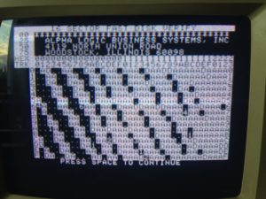
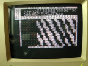
If the problems still persist a recalibration of the drive’s mechanics and/or electronics might be helpful. If you have a copy of Locksmith at hand you might try to do a fast disk verify scan with a known good disk. Drives that need a recalibration can show a very distinct scan pattern of a known good disk with a sequence of alternating good and bad sectors on each track. The following picture shows a scan result of a drive with a misaligned read/write-head position:
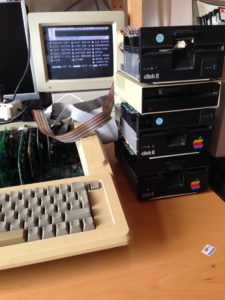
Before you start you should prepare the following:
- Known good drive as Drive 1 and drive to calibrate as Drive 2 connected to the controller
- Disk Aligment Aid program disk for booting in Drive 1
- Test disk for Drive 2 – caution: the calibration procedures will erase data on the test disk in Drive 2!
- An oscilloscope for analog signal measurements during the calibration process (at least 20 MHz bandwidth!)
- Some tools to open the casing of Drive 2. The casing should be removed completely from the drive in order to access the analog board as well as the stepping motor for the head positioning
- For testing the success of your calibration measures you can use a tool like Locksmith to perform some disk scans of known good disks and formatting/copying of some test disks in order to ensure that the drive works properly after you recalibrate it.
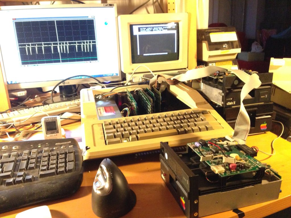
Your test setup could look like this here:
Before you try to recalibrate
It is a good advice to perform two of the described tests in the Apple Disk ][ Technical Procedures before you try to do any recalibration attempts. The two tests are:
- Amplitude test
- Azimuth test
Both tests can can be performed without doing any mechanical adjustments or changes to the drive just by measuring signals from the analog board in the disk drive. It is a good idea to try these tests before you try to do mechanical changes to the drive’s head moving assembly.
Amplitude test
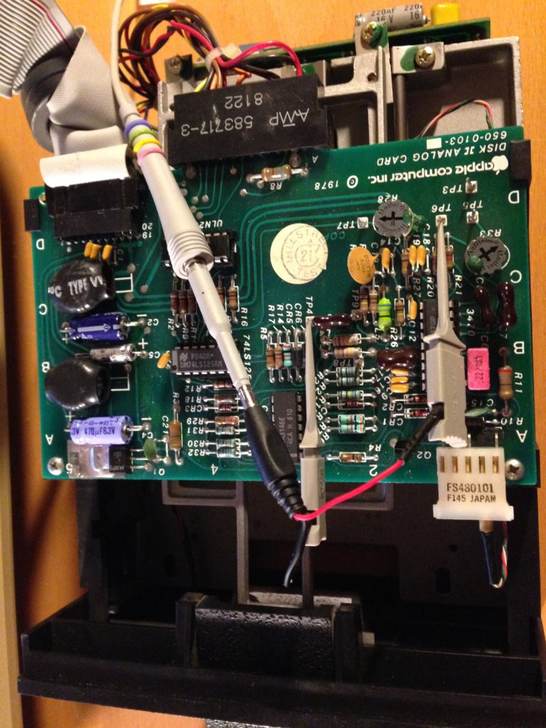
The amplitude tests checks if the drive electronics produce a large enough signal for the drive to operate normally. It is described from page 3.4 on in the Disk ][ Technical Procedures and should be followed according to the description there. It is a quite straightforward test. Be sure to use a scratch disk in the drive to test since the drive is erasing data on the test disk in order to record a sine-signal which is then read by the drive. The following image shows my test probes connected to the analog board of the Disk ][:
Azimuth test
This test gives you a feedback if the head position is perpendicular to the track on the disk. The test is described from page 3.7 on. Some possible oscilloscope patterns which you might see on your scope are given on page 3.10. You should carefully check if your measured pattern is one of the acceptable ones for each track tested. I found it to be a bit difficult to properly recognize the patterns and to decide if they belong to one of the acceptable ones.
If you encounter an unacceptable pattern it is likely that your drive is mechanically out of calibration, especially if unacceptable patterns occur in inner- or outermost head positions (tracks 0 and 34). It is also possible that the analog board is buggy. This might be the case if all patterns at any head position (tracks 0 to 34) are unacceptable.
Mechanical recalibration procedures
There are two mechanical recalibration procedures described in the Disk ][ Technical Procedures:
- Carriage limiter adjustment
- Head radial adjustment
From my point of view you should perform both starting with the carriage limiter adjustment
Carriage limiter adjustment
This procedure is described from page 3.11 on and is a rather rough adjustment for the head finding the correct position for track 0 while trying to boot. This adjustment can be performed pretty easily. However, from my experience, most drives do not benefit much from this adjustment.
Head radial adjustment
This adjustment procedure might be the sacred cow since it really is a bit of a tricky task which can leave the drive in a state worse than before. This adjustment is seen as a fine tuning of the head position after you have performed the carriage limiter adjustment. Regarding the fact that this adjustment requires to loosen the two screws holding the stepper motor of the drive head in position and moving it to another position depending on the signal display on an oscilloscope makes this task rather demanding regarding your fine-motor skills and perseverance.
The procedure is described from page 3.14 on. Page 3.16 shows the required scope display at the correct stepper motor position. Page 3.17 shows the positions of the two screws which hold the stepper motor in place. Beware not to loosen these screws to far giving the stepper motor too much slack while adjusting! Try to move the motor only very small steps in one direction in order to find the optimum signal display on the scope. If the signal gets worse reverse the direction of your movement of the stepper motor.
If you have found the “optimum” position for the stepper motor then do not forget to tighten the screws carefully before you continue with the tests and issue the “recalibrate” command (as required in the technical documentation) since this will exert a significant force on the stepper motor which might immediately distort your arduous calibration work so far!
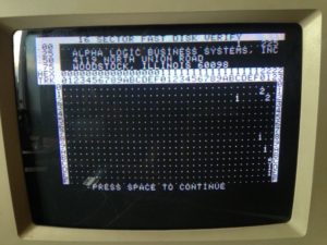
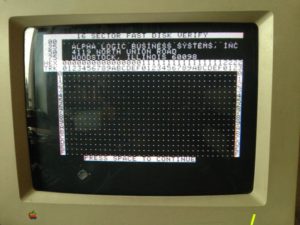
From my experience this calibration step is the most difficult and may take quite some time and different attempts in order to find the best stepper motor position. Calibrating the system using only the oscilloscope feedback was often tedious and led to unsatisfactory results, i.e. the oscilloscope signal was nice but the drive was not able to read known good disks properly. Hence I used the Locksmith disk verify option as a validation procedure in order to get the best recalibration results.
The following sequence shows different Locksmith scans of a known good disk at various stepper motor positions:
Last but not least – electronic recalibration
A few words about the recalibration of the comparator circuit. Most analog boards have two potentiometers which allow to recalibrate the comparator circuit. This circuit ensures that a “one” is stored as one and a “zero” is stored as a zero on the disk.
This adjustment is described from page 3.20 on and is from my point of view a relatively easy to perform task if the analog board is working properly. Some analog boards have only one or even no potentiometer. If the comparator adjustments are not possible or cannot be performed due to the lack of the potentiometers you might have to replace the analog board of the drive. Most drives I have tested did not need a comparator recalibration.
Conclusion
Intense use, longtime storage and other mechanical wear of a Disk ][ might require a thorough recalibration in addition to an overall cleaning procedure of the drive and its read/write-head.
The electrical and mechanical recalibration can be performed with some patience but require electronic lab equipment e.g. an oscilloscope. The most crucial step is loosening the screws of the stepper motor since this maneuver can result in a drive state worse than before. Most old drives which I came across which did not work after extensive cleaning and speed adjustments could be brought back to life by following the procedures described above.
However, one pitfall which should be kept in mind is a malfunctioning analog board which can present a behavior comparable to a mechanical failure. This fact should be remembered if all mechanical adjustments remain unrewarding.
Good luck!
(Author: Marc A. Golombeck)